Thermal Comparison of Plain-Faced and Cross-Drilled/Slotted Vented Brake Rotors
BMW E90 M3 Inspired 360 mm Rotor Concept | Personal Engineering Project
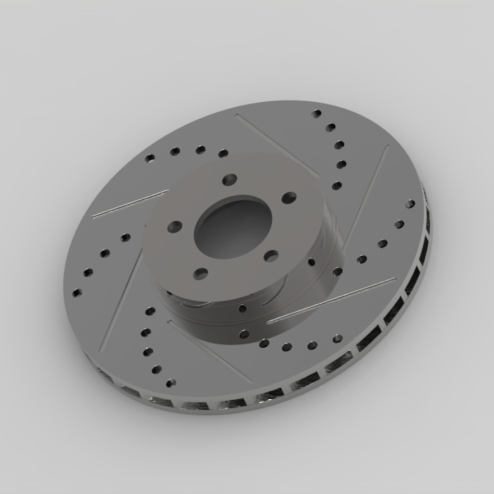
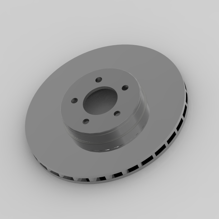
Project Overview
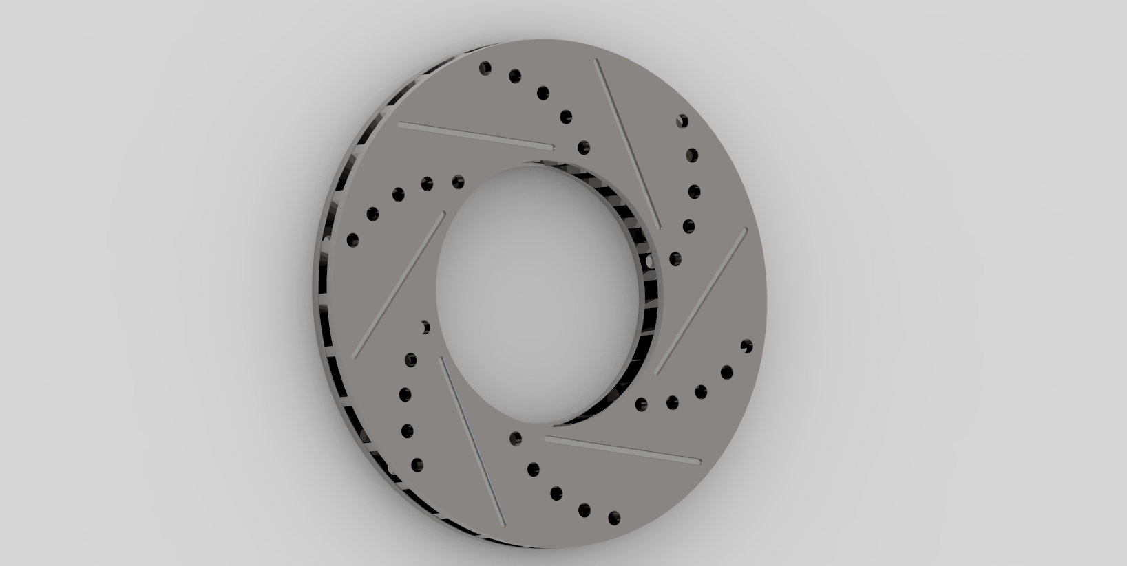
I designed two ventilated brake rotor concepts in CREO Parametric using dimensions of the BMW e90 M3 front brakes found online to explore how drilling and slotting affects thermal behavior during a 60-0mph 5 second braking event. The study compares a plain vented rotor with a cross-drilled and slotted variation. Both models used the same overall geometry, internal vane pattern, material, and heat input. The friction-surface features were the only intended design change.
What’s the Objective?
Drilled and slotted rotors are often associated with improved thermal performance, but their surface features also remove material that stores heat. This study evaluated the tradeoff between added exposed surface area and reduced thermal mass by comparing peak temperature and cooldown behavior between the two rotor designs.
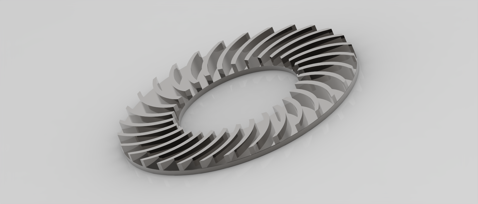
Simulation Setup
Material used: CAST-IRON
25 °C ambient air
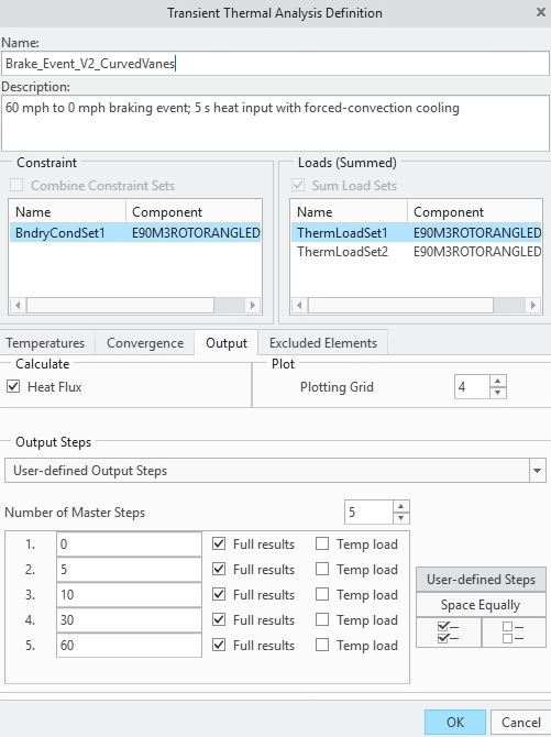
Two friction-based heat sources were used, both 18.5 kW. They were placed on both the front and back faces, for a total of 37 kW for one rotor.
A function of time was setup to stop the heat after 5 seconds of braking
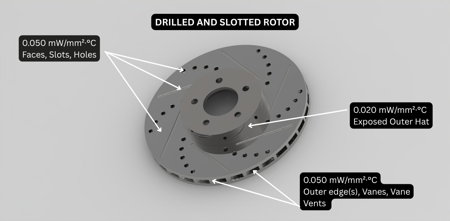
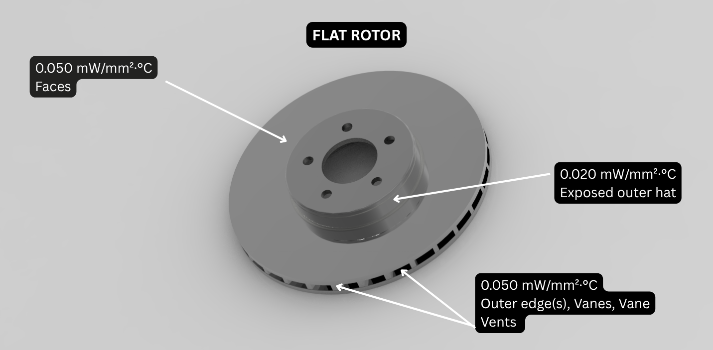
Different enviroment based convection coefficients were placed anywhere where there would be direct contact to air. The only difference in each model was the addition of the convection applied to the drills and slots in the respective rotor.
Due to some issues I ran into that the simulation would not run properly, I used the user-defined output steps feature at times ranging from 0-60s so the data could be comparable at different stages. (see below)
Convection Diagrams
Results
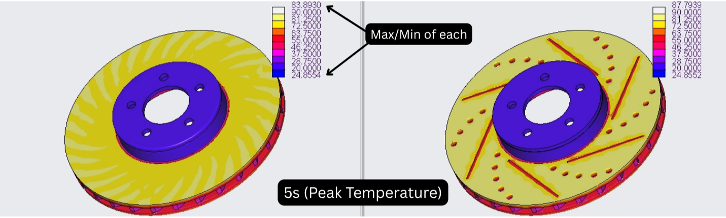
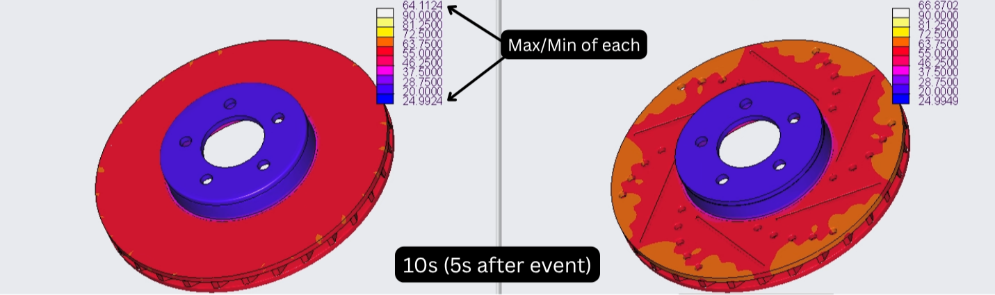
At the end of the braking event, the drilled/slotted rotor reached a 4.7% higher maximum temperature and showed lighter thermal gradients around and inside the drilled holes and slots. The plain-faced rotor maintained a more uniform temperature field across the friction ring.
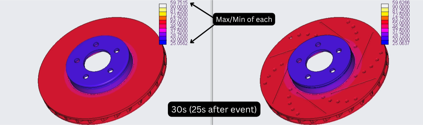
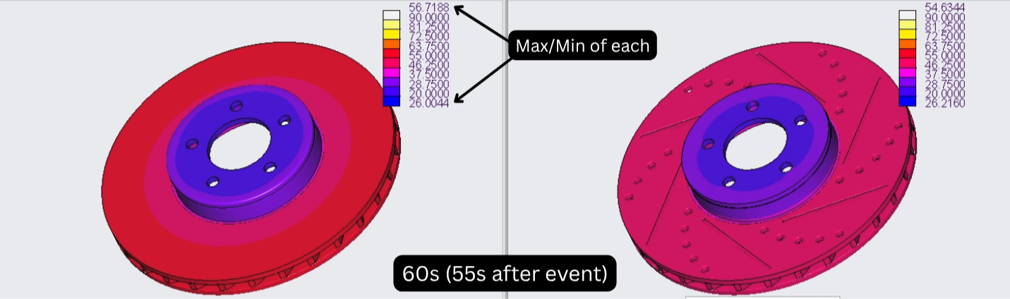
During the cooldown period, the temperature difference steadily decreased. By 30 seconds, the two designs reached almost equal maximum temperatures. By 60 seconds, the drilled/slotted rotor was 2.1 °C cooler than the plain-faced baseline.
(All pictures seen are thermal maps of the events during different time stages)
| Time | Plain Faced Rotor | Drilled/Slotted Rotor | Difference (Drilled-Plain) |
|---|---|---|---|
| 5s | 83.9 °C |
87.8 °C | +3.9 °C (+4.7%) |
| 10s | 64.1 °C | 66.9 °C | +2.8 °C (+4.3%) |
| 30s | 59.8 °C | 59.6 °C | −0.2 °C (about equal) |
| 60s | 56.7 °C | 54.6 °C | −2.1 °C (−3.7%) |
Key Takeaway
These results display a time-dependent tradeoff of a higher peak temperature for the drilled and slotted rotor, while providing quicker overall cooling time for the time range given (60s). At the end of the 5-second braking event, the cross-drilled and slotted rotor reached a 4.7% higher maximum temperature than the plain-faced baseline. Its reduced material volume limited its ability to absorb the same braking energy during the short heat-input period. This result doesn’t indicate which is better, because this does not evaluate stress or strain over time, thermal fatigue, as well as many other factors I may not be familiar with yet.
During the cool-down period is where the added convection exposure really helps the drilled/slotted rotor, by providing enough cooling to eventually pass the plain faced rotor despite the higher peak temperature. By 30 seconds, both rotors reached nearly equal maximum temperatures and by 60 seconds, the drilled/slotted rotor was 2.1 °C cooler. This indicates that the added air-exposed area from the holes and slots became more influential after braking ended.
My main takeaway from this is not that drilled/slotted rotors are always better for every situation. Rather, this model shows that in very simple designs, they can trade a higher short duration peak temperature for improved post-braking cooling. The result also indicates why rotor design is so important and how decisions must take into account thermal mass, airflow, surface area, and durability rather than relying on one performance spec alone, especially when it comes to designing brakes for performance use.
What Did I Learn?
Overall, this project has taught me a good bit and also refreshed me on things I haven’t done in a while. Here are some things I learned, along with issues I encountered while building the rotor or doing the thermal analysis:
-Relying on Vague or Hard to Understand Dimensions then Converting them to Reality
It was very hard to find the exact dimensions of these rotors online. I would have chosen easier dimensions to find but I love this car and understood that I probably shouldn’t just guestimate dimensions. I found the dimensions off of an online forum, M3post. I will not know if they are exactly accurate however all the dimensions I was able to convert off this list given.
Trying to accurately pattern the cross-drilled holes using a reference picture off google was different, but eventually through screenshots which turned into makeshift blueprints, I was able to make it work. I had to take a screenshot of the rotor as it is normally, mark where I wanted the holes to begin and end, as well as the track I want it to take, then suppress the top face and line them up with the screenshot. It took me a while to even come up with this idea but when I did, it made my life significantly easier.
-How to Create Heat as an Event in Creo and Measure the Cooldown
Previously, I had only briefly done transient temperature studies in class, and it never involved comparing results or measuring what design is better in the cooling process. This project has taught me a lot about that, and how creating temperature as a function of time can help setup an event that has a measurable outcome.
Finding the values for the heat sources using kinetic energy was enjoyable, as I could finally apply the physics I have been learning in class into something that is tangible.
Additionally, I learned how to setup a direct comparison after both models had been analyzed by ensuring the legend was consistent and removing labels or tags to make the image more visually appealing.
Initially, my results weren’t fully accurate. The first many tests that I did comparing the two, the solid rotor was constantly significantly cooler than the drilled and slotted rotor. I brought this to the attention of my dynamics team lead in the FSAE club unintentionally, and quickly I realized the issue was that I created the facilities for airflow, but never actually added the airflow itself to the drills and slots. Fixing this error fixed my results and finalized my project.
-The Render Feature
Before I learned how to use the render feature, a large majority of the pictures I was planning on using were taken using the snipping tool. I did some research and was able to easily upgrade these pictures and also get some pretty cool angles.